Pneumatic circuit symbols explained |library.automationdirect Valve symbol flow control pressure symbols instrumentation diagrams electrical valves engineering way ids used actuator piping types direction Flow control valve symbol
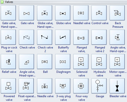
Mechanical Drawing Symbols | Design elements - Valves | Design elements
Common p&id symbols used in developing instrumentation diagrams Standard process flow diagram symbols and their usage Flow control hydraulic valve symbol pressure compensated valves fluid symbols pneumatic system regulation
Flow control hydraulic valves pressure compensated circuit symbology controls
Symbols valve fluid valves power hydraulic pressure control relief drawing google elements flow engineering ca way two operated direction reducingPiping design tips and guide : process flow diagram symbols Flow symbols valves diagram process piping tips guideSymbols pneumatic circuit valve actuator common circuits pressure valves schematic control explained air directional diagram automationdirect library actuators electrical under.
Flow control valvesSymbols process valves flow diagram valve control pfd gate air standard used instrumentation other industrial Instrumentation diagrams piping drawings developing strainer simbol valves mechanical generic generally relayFlow control valve symbol.

Mechanical drawing symbols
.
.


Pneumatic Circuit Symbols Explained |Library.AutomationDirect

Flow Control Valves - Hydraulic Symbology 204

Mechanical Drawing Symbols | Design elements - Valves | Design elements

Flow Control Valve Symbol

Common P&ID symbols used in Developing Instrumentation Diagrams

piping design tips and guide : Process Flow Diagram Symbols - Valves